 StickContour
Deforms the Deformable Geometry using two contours that are specified on the surface of a Template Geometry and stuck together in various ways, possibly using contour positions on the Deformable Geometry or a separate Reference Geometry if provided, or even using Screen Points produced by Detection-related nodes, by hand using SelectScreenPoints node etc.
How It Works
Attention
The node is sensitive to intersections on the Template Geometry. Although it is not necessary, it is advised to apply FixIntersections to the Template Geometry if it happens to have intersections in the general area where contours are.
This node is primarily used to fully or partially close surfaces like lips and eyes on blendshapes or 4D sequences, typically results of retargeting. In any case, graph view of the correct usage of the node is depicted below
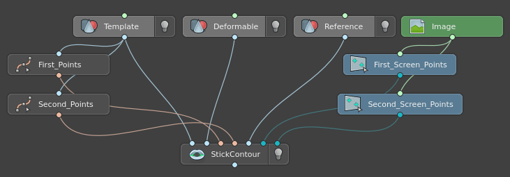
First input is supplied with a Template Geometry. Ideally, this is a neutral geometry with surfaces of interest not fully closed. This is both to aid actual markup of contours and to ensure that the node correctly processes these contours.
Tip
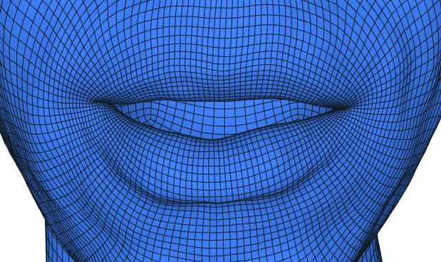
Example of a good geometry to use as a Template Geometry. Notice how it does not feature complicated expressions, only has it’s lips open.
Second input is supplied with a Deformable Geometry. This is the actual geometry to stick surfaces with contours in. It does not need to meet any specific criteria, other than that it needs to be in the same topology as Template Geometry.
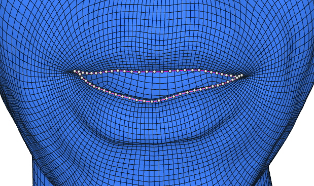
The next two inputs are supplied with Points that comprise contours. It is recommended that contours are created on a Template Geometry, since this is where they are going to be processed.
The next input is optionally supplied with a Reference Geometry. It provides geometric data in some of the contour sticking modes.
The last two inputs are optionally supplied with Screen Points. They are used in some of the contour sticking modes.
When all the necessary inputs are present and valid, the node goes through two phases to calculate final geometry with stuck surfaces.
1. Contour Calculation Phase
This phase determines contours on the Deformable and Reference geometries to use for sticking.
Contour Type: Points On Triangle
If contour type is Points On Triangle, contours for both geometries are taken from Points inputs as is. This contour type can be used when input geometries are sufficiently similar geometrically, that is, when contours on Deformable Geometry do not move away from the region of interest as specified on the Template Geometry.
Contour Type: Offset Trace
If contour type is Offset Trace, contours are calculated to better fit the “sticking” regions of Deformable and Reference geometries. The process goes as follows.
Contours are first offset inside the Template Geometry. This process is controlled by numerous offset-related parameters. After that contours are deformed to fit Deformable and Reference geometries in a fashion similar to how Lattice deforms geometries. Finally, contours are traced back onto each geometry individually to obtain corrected contours to use in Deformation Phase.
Tip
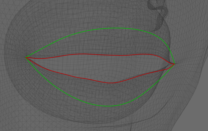
This node features a Visual Editor that may provide useful information to use when adjusting parameters. Namely, for Deformable and Reference Geometry, deformed and cast contours are displayed.
Green contours are offset contours deformed from Template Geometry. If contour type is Points On Triangle, these are not displayed.
Red contours are contours traced onto a respective geometry.
2. Deformation Phase
In this phase, contours obtained from a previous phase are used to deform the Deformable Geometry.
First, contours are stuck in different ways depending on the selected Mode. For every pair of points on contours a specific Stick Value is assigned. This value is a number between 0 and 1 that determines how much to stick the two points of this pair.
Then, for every vertex of Deformable Geometry in close proximity to the respective contour a closest point on a contour is calculated. Stick Value for this point is interpolated between closest control points.
Finally, based on the distance from a vertex to it’s closest point on a contour and this point’s Stick Value, this vertex is translated. On a larger scale this translation of many points closely resembles the transformation that contours undergo after sticking.
Below are smooth blends between initial geometry and “stuck” one for Manual and Stick By Distance modes. Animation is used to illustrate the deformations of each vertex.
Manual

Stick By Distance
Inputs
- Template Geometry
GeometryNeutral geometry used for contour markup.- Deformable Geometry
GeometryGeometry to deform with contours. Has the same topology as Template Geometry.- First Contour Points
NamedPointsOnTriangleAn ordered set of points on Template Geometry that specify first contour.- Second Contour Points.
NamedPointsOnTriangleAn ordered set of points on Template Geometry that specify second contour. Must have the same number of points as First Contour Points.- Reference Geometry
Geometry(optional) Geometry to take distance information for Close By Reference and Stick By Reference modes. Has the same topology as the other two.- First Screen Points
ScreenPoints(optional) An ordered set on points on an image that specify first screen contour for Close By 2D Reference and Stick By 2D Reference modes. Does not need to have the same number of points as Contour Points.- Second Screen Points
ScreenPoints(optional) An ordered set on points on an image that specify second screen contour for Close By 2D Reference and Stick By 2D Reference modes. Does not need to have the same number of points as First Screen Points.
Tip
Even though Contour Points may be of any origin, it is highly recommended to use SelectPointsWithSplines to generate points for both contours.
In particular, it allows to specify contours with any level of detail and then resample it to have a fixed number of points. This helps preserve surface detail of the geometry and have both contours contain the same number of points.
Output
- Geometry
GeometryGeometry deformed with contours.- First Calculated Reference Contour
NamedPointsOnTriangleDeformed First Contour Points.- Second Calculated Reference Contour
NamedPointsOnTriangleDeformed Second Contour Points.
Parameters
- Deformation Radius (cm):
Max distance at which contours affect the Deformable Geometry. Gets smaller near contour ends.
- Contour Type:
- Points On Triangle
no processing is performed on input contours, the Deformable Geometry gets deformed with them.
- Offset Trace
contours are offset inside the Template Geometry, deformed to fit the Deformable Geometry and the Reference Geometry, if specified, and then traced back onto the surface of each geometries. Resulting contours are used to deform the Deformable Geometry.
- Offset Distance (cm):
Distance, with which contours are offset into the Template Geometry.
- Offset Attenuation:
Limits the portion of the contour that is affected by offset. For example, if it is set to 0.5, only the middle half of the contour is affected by offset.
- Offset Falloff Type:
- Steep
offset falls off steeply closer to the edges.
- Smooth
offset falls off smoothly closer to the edges.
- Offset Lattice Radius Middle (cm):
Max distance, at which vertices of the Template Geometry affect the contour deformation during the Offset Trace phase. Specifies the distance in the middle of the contours.
- Offset Lattice Radius Corner (cm):
Same as Offset Lattice Radius Middle, but specifies the distance at contour edges.
- Use Geodeic Lattice:
If set, vertices of the Template Geometry affected by the contours are calculated on geometry geodesic.
- Mode:
- Manual
contours are stuck uniformly with adjustable Stick Value.
- Stick By Distance
contours are stuck non-uniformly based on the distance between contour points on Deformable Geometry.
- Close By Reference
contours are stuck uniformly based on the “area” of a region made by contours on Reference Geometry.
- Stick By Reference
same as Stick By Distance, but the distance information is provided by Reference Geometry.
Manual Tab
- Stick Value:
Extent to which contours are stuck. 0 means not at all, 1 means fully stuck.
- Contour Bias:
Contours stick closer to one of the initial contours based on this parameter. -1 sticks contours closer to the first contour, 1 sticks closer to the second, 0 stick precisely in the middle.
Stick By Distance Tab
- Stick Distance (cm):
Distance, at which contour point is considered fully stuck.
- Stick Falloff (cm):
Distance, at which contour point is considered partially stuck.
- Falloff Type:
- Linear
linearly interpolates the Stick Value for a given point between Stick Distance and StickDistance + Stick Falloff.
- Smooth
interpolates the Stick Value for a given point between Stick Distance and StickDistance + Stick Falloff using the smoothstep function.
- Expand Iterations:
Number of times the “fully stuck” region of the contours is extended by a single point.
- Smooth Iterations:
Number of times the Stick Values of the “partially stuck” region of the contours is smoothed.
- Smooth Neighbours:
Number of neighbouring points used during Stick Value smoothing.
- Pin Borders:
Specifies whether the “fully stuck” region of the contours should remain fully stuck during Stick Value smoothing.
Close By Reference Tab
Note
This mode requires Reference Geometry to work. It works by approximating the area of a region between the two contours on Reference Geometry. Stick Value is decided for the entire contour using that approximation.
- Reference Closing Threshold:
Area, at which contour is considered fully closed.
- Reference Closing Falloff:
Area, at which contour is considered partially closed.
- Falloff Type:
- Linear
linearly interpolates the Stick Value for the contour between Reference Closing Threshold and Reference Closing Threshold + Reference Closing Falloff.
- Smooth
interpolates the Stick Value for the contour between Reference Closing Threshold and Reference Closing Threshold + Reference Closing Falloff using the smoothstep function.
Stick By Reference Tab
Note
This mode requires Reference Geometry to work. It works by taking distance information from that geometry and not from Deformable Geometry. Other than that, this mode is identical to Stick By Distance mode.
- Reference Distance (cm):
Distance, at which contour point is considered fully stuck.
- Reference Falloff (cm):
Distance, at which contour point is considered partially stuck.
- Falloff Type:
- Linear
linearly interpolates the Stick Value for a given point between Reference Distance and Reference Distance + Reference Falloff.
- Smooth
interpolates the Stick Value for a given point between Reference Distance and Reference Distance + Reference Falloff using the smoothstep function.
- Expand Iterations:
Number of times the “fully stuck” region of the contours is extended by a single point.
- Smooth Iterations:
Number of times the Stick Values of the “partially stuck” region of the contours is smoothed.
- Smooth Neighbours:
Number of neighbouring points used during Stick Value smoothing.
- Pin Borders:
Specifies whether the “fully stuck” region of the contours should remain fully stuck during Stick Value smoothing.
Close By 2D Reference Tab
Note
This mode requires Screen Points to work. It works by approximating the area of a region between the two screen contours with resolution specified in the Screen Resolution parameter. Stick Value is decided for the entire contour using that approximation.
- Screen Resolution:
Resolution to use for screen contours.
- Pixels per Centimeter:
Conversion quotient between screen’s pixel scale and geometries’ scale.
- 2D Reference Closing Threshold:
Area, at which contour is considered fully closed.
- 2D Reference Closing Falloff:
Area, at which contour is considered partially closed.
- Falloff Type:
- Linear
linearly interpolates the Stick Value for the contour between 2D Reference Closing Threshold and 2D Reference Closing Threshold + 2D Reference Closing Falloff.
- Smooth
interpolates the Stick Value for the contour between 2D Reference Closing Threshold and 2D Reference Closing Threshold + 2D Reference Closing Falloff using the smoothstep function.
Stick By 2D Reference Tab
Note
This mode requires Screen Points to work. When Copy Distance feature is disabled, it works by taking distance information from these screen contours and not from Deformable Geometry. Other than that, this mode is identical to Stick By Distance mode.
- Copy Distance:
Enables sub-mode of this mode that directly copies screen contours’ distances to Deformable Geometry, only applying screen->modelspace conversions using the next two parameters.
- Screen Resolution:
Resolution to use for screen contours.
- Pixels per Centimeter:
Conversion quotient between screen’s pixel scale and geometries’ scale.
- Screen Point Offset:
Number of input screen points ignored from both ends of the screen contours.
- 2D Reference Distance (cm):
Converted distance, at which contour point is considered fully stuck. Disabled if Copy Distance is active.
- 2D Reference Falloff (cm):
Converted distance, at which contour point is considered partially stuck. Disabled if Copy Distance is active.
- Falloff Type:
- Linear
linearly interpolates the Stick Value for a given point between 2D Reference Distance and 2D Reference Distance + 2D Reference Falloff.
- Smooth
interpolates the Stick Value for a given point between 2D Reference Distance and 2D Reference Distance + 2D Reference Falloff using the smoothstep function.
- Expand Iterations:
Number of times the “fully stuck” region of the contours is extended by a single point. When Copy Distance is active, it just changes the Stick Value to a minimum of it’s two immediate neighbours.
- Smooth Iterations:
Number of times the Stick Values of the “partially stuck” region of the contours is smoothed.
- Smooth Neighbours:
Number of neighbouring points used during Stick Value smoothing.
- Pin Borders:
Specifies whether the “fully stuck” region of the contours should remain fully stuck during Stick Value smoothing. Disabled if Copy Distance is active.