 ImageFacialWrapping
Only in Wrap4D
Uses a set of personalized blendshapes and textures to fit geometry to input images.
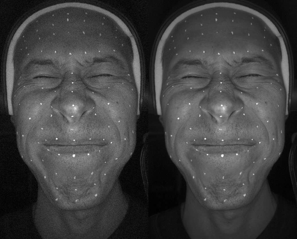
This node is analogous to the combination of the FacialWrapping and OpticalFlowWrapping nodes for images. The node accepts input images and their corresponding cameras instead of scans. Currently, work with one stereo pair (2 cameras) is supported.
It lies at the heart of the HMC image-based 4D processing pipeline. To process a sequence, you just need to evaluate the ImageFacialWrapping node for each frame of the sequence. Each frame can be computed independently, so the entire sequence can be computed in parallel.
The core idea of the node is to deform the geometry and mix the textures of the actor in such a way that the final render best fits into the target input images. The algorithm also takes into account the depth of the scene in order to hit the real face.
To help the wrapping process, it is very desirable to pass information about the facial detections and markers that were received in the Track to the input.
To control the deformable geometry, a sampling mask is used, which is responsible for flexibility. And to control regions that are poorly visible, the uncertainty mask is used.
Note
The more vertices the topology contains, the more accurate the final result will be, but the computation time will increase significantly.
We suggest using a topology with 20.000 - 50.000 vertices.
Common Usecase
A common use case is to fit some initial geometry with textures to target images. At the moment, the main use case is the 4D processing pipeline for the HMC. This process can be divided into several steps:
preparing two calibrated cameras using Stereo Camera Calibration Tool. Or you can use cameras obtained in another way, you can read more about supported formats in the Camera;
fitting the position of the initial geometry to the cameras, which can be done using the AlignGeomToCameras node. It is necessary that the initial geometry be visible through the cameras. This can also be done manually;
creating a Facial annotate with a FacialAnnotation node. This step is required if you are going to use Facial detection from Track;
labeling markers on initial geometry corresponding to markers on images that come from Track;
fitting initial geometry to images with ImageFacialWrapping node.
post-processing results with GuidableHeadStabilization, GuidableReplace, GuidableDeltaMush, GuidableMesh and GuidableTexture;
FacialWrapping vs ImageFacialWrapping
ImageFacialWrapping, although similar to FacialWrapping, has a number of significant differences:
uses only camera images instead of scans, like the OpticalFlowWrapping node. This allows you to get a more accurate result, especially with a limited number of cameras, since images contain more information than a scan and have no noise;
uses personalized stabilized blendshapes as Reference Blendshapes. This is a necessity that is needed due to the limitations of cameras;
uses personalized textures. This is necessary to simulate wrinkles and blood flow on the face;
uses Illumination Simulation to better render geometry into target images;
uses sampling and uncertainty masks for more control over deformation.
Reference Blendshapes
As already mentioned, ImageFacialWrapping needs a set of examples provided by a user called reference meshes. All reference meshes should have the same topology as a the intial geometry.
Reference meshes include:
- Neutral Reference
is a neutral facial expression of a reference character. Must match the scale with the initial geometry.
- Blendshape References
is a set of stabilized blendshapes (FACs) of your reference character.
All Blendshape References should be aligned (stabilized) to the Neutral Reference and have the same scale. It is desirable that Blendshape References cover as much variety of actor face shapes as possible.
It’s not mandatory that Blendshape References are decomposed by muscle groups as you would do for rigging. I.e. if Blendshape References contain an expression with both-eyes-closed, then there is no need to decompose it into left-eye-closed and right-eye-closed. The algorithm will still be able to wrap an expression with only one eye closed.
Note
If you use non-stabilized geometries, then the Dynamic texture and Uncertainty mask do not make sense, and rather harm. Therefore, it is better to turn off these options for wrapping.
Sampling Mask
During the wrapping process, the Coarse-to-Fine process takes place, as a result of which the geometry beats into separate pieces. This approach can be seen in every wrapping node. The smaller the partition, the tighter the fit of the geometry to the target. This node is no exception.
The main feature is that most of the geometry is out of view of the cameras. Therefore, it makes no sense to finely subdivide sections of geometry that are not visible.
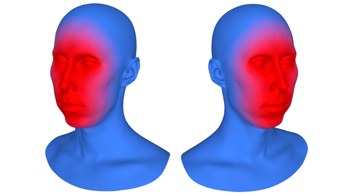
For this reason, a mask is added that explicitly divides the geometry into two zones: well visible (inside) and poorly visible (outside). For each zone, you can set the radius range in the sampling tab.
Uncertainty Mask
Due to limited field of view, we may not be sure about some regions as they are hard to see. For example, this is the area along the edges of the nasal septum, the back of the head, the edges of the cheeks or the chin.
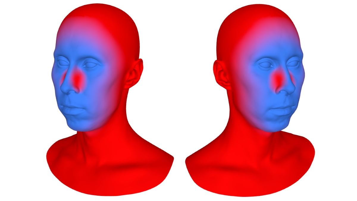
Therefore, we can explicitly specify such areas using a mask. The algorithm is similar to the GuidableReplace node. The marked regions will be more predictive based on the Blendshape References. How much is determined by Uncertainty Region Weight.
Tip
Very often the Uncertainty mask is the invert of the Sampling mask with a few tweaks. This fact can simplify the process of its creation, since it is enough to invert the Sampling mask.
Dynamic Texture
The main task of the node is to deform the initial geometry in such a way that its render with texture best matches the target images. The more similar the render is to the target image, the more accurate the result will be.
To increase the similarity of the render and target images, a dynamic texture is used. The idea and settings are similar to the GuidableTexture node. In the process of wrapping, based on the reference geometries and the corresponding textures in the textures tab, a texture is generated that will correspond to the current state of the geometry.
Note
Geometry reference for textures may differ from the main reference geometries.
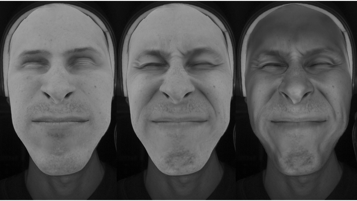
Below is an example of what the target image looks like, rendered with a neutral texture and a dynamic texture.
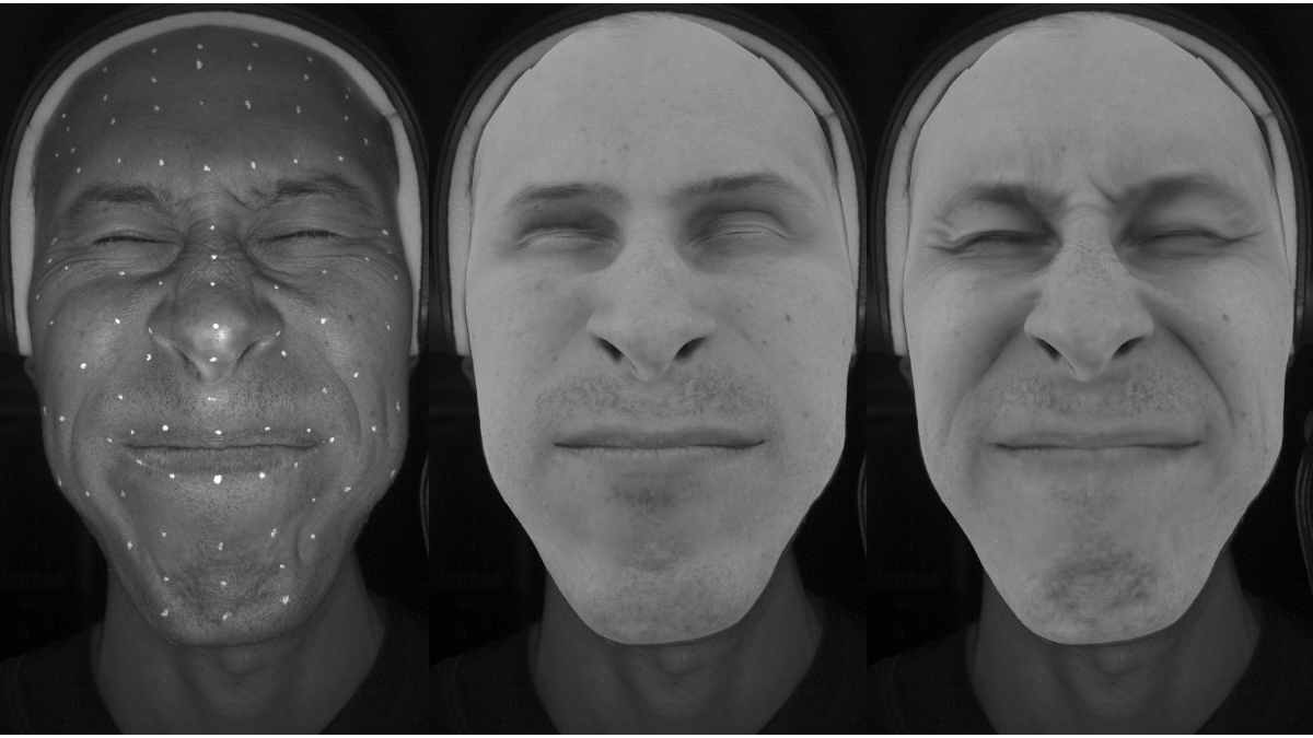
Textural details appear that meet the target, they help in the wrapping process to better get the render into the image. But this is often not enough if the textures were shot in a different light. For this, the Illumination Simulation option is used.
Note
If the Dynamic Texture option is disabled, then the texture from the Initial geometry that goes to the input will be used.
The number of Blendshape Reference Meshes and Blendshape Reference Textures must match, as well as the order. Be careful when choosing textures and geometries in the window dialog.
Tip
Dynamic Texture computation requires a lot of RAM and takes time to calculate, but the wrapping process does not require high resolution textures.
Therefore, you can use the Texture Donwscale parameter to reduce the input textures. Resolution 2048x2048 is enough. Or you can preload textures of the desired resolution and set the parameter to 1.
Loading textures of an already required size is desirable, as the least amount of RAM will be required.
Illumination Simulation
If the textures were obtained in illumination that is different from the illumination in the image, then this option is used. Illumination is simulated to best match natural light in images.
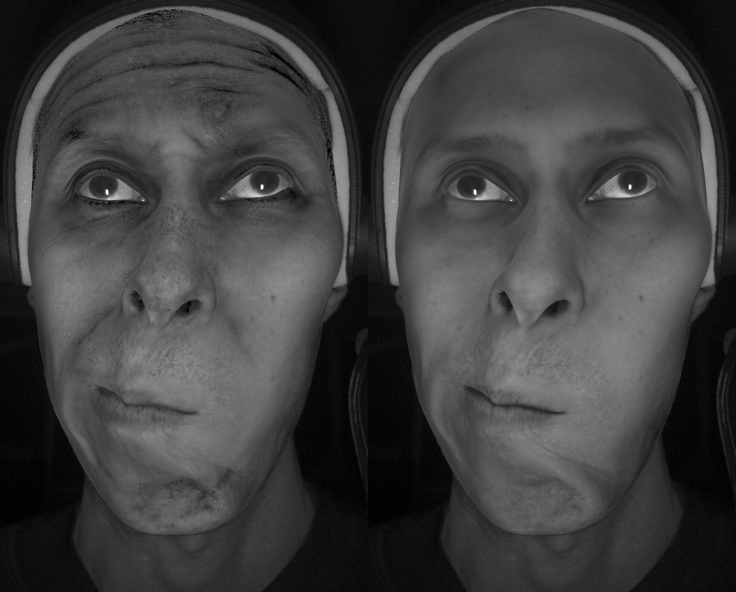
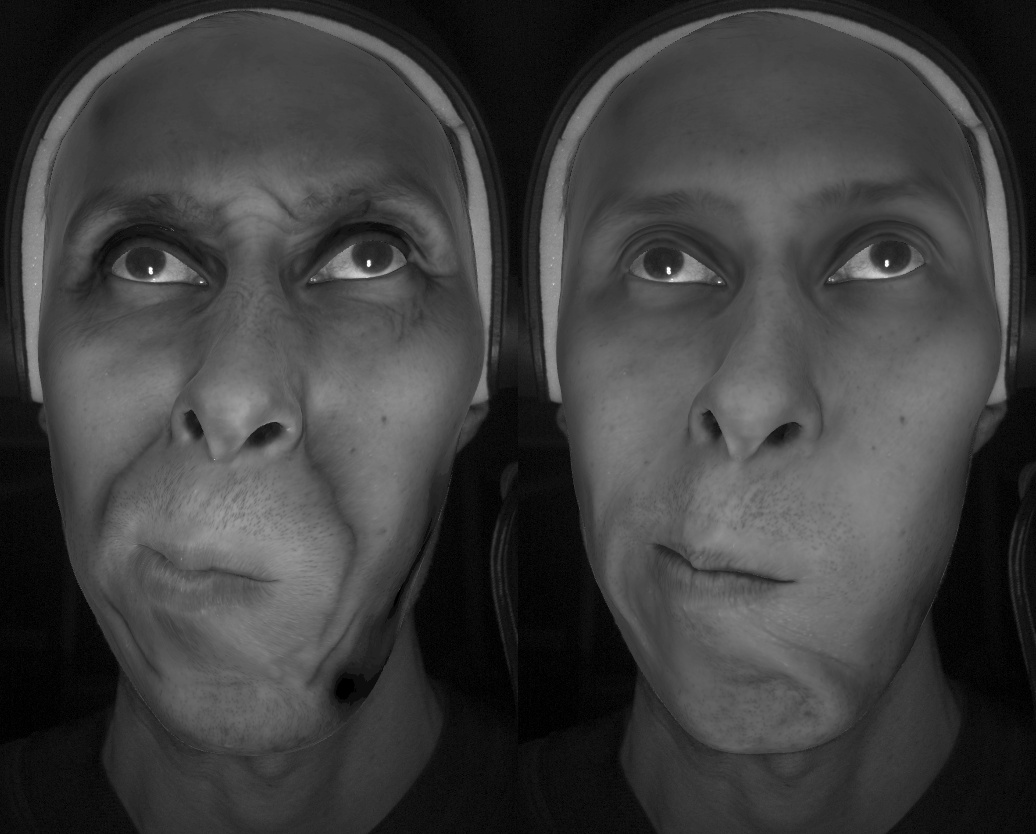
Below is an example of how the render looks like with a neutral texture, dynamic and dynamic with illumination simulation.
Note
This option can be applied both with Dynamic Textures enabled and disabled. The illumination will then be applied to the texture of the Initial geometry.
Tip
For best performance of Illumination Simulation it is desirable to use cross-polarized textures.
Iterations
A computation is performed in several iterations. There are pairs of node parameters with “Range” word. The values of such parameters are changed with each iteration starting from the first value up to the second value.
For example, the Image Width Range parameter sets the initial width of the images (the height is calculated automatically to maintain aspect ratio) and the final value. During the wrapping process, with each new iteration, the size of the images will change linearly from the first value to the second. When increasing the final resolution, it is also necessary to increase the number of Downsample Iterations.
Similarly, with each new iteration, a large number of parameters change. Some of them should be increased towards the end, or reduced. For more information about what to do with each parameter, see the description of the parameters.
Editor
The ImageFacialWrapping node has a visual editor that has two viewports. The left one displays the image through the first camera. In the right through the second camera. Facial annotation and Facial detection are optionally displayed in each of the viewports, as well as markers both on images and on the basemesh.

Show |
сan be used to select the display mode for geometry on the target image |
Texture |
сhoosing which texture to display on the geometry, or not to display at all |
Points |
enabling the display of markers on the image and on the geometry |
Names |
enabling the display of markers names. May be useful for checking matches |
Detection |
enabling the display of Facial detection and Facial annotation |
Note
Fitting only works in areas of a mesh that are observed by cameras. The rest of the mesh is deformed as rigid as possible.
Inputs
- Initial Geometry
GeometryGeometry to be deformed (a basemesh). Must be approximately aligned to the Cameras- Markers on Initial Geometry
NamedPointsOnTriangle(optional) Array of named points on initial geometry. Names must match Screen points- Excluded Floating Polygons
PolygonSelection(optional) A set of polygons that will not be fitted to images but will be deformed as rigidly as possible to match the rest of the mesh. However, markers included in these polygons will still fit.- Cameras
Cameras(multiple) The position and settings of the cameras correspond to the Images. Only 2 cameras can be used at the moment- Images
Image(multiple) A set of images corresponding to Cameras. Based on them, the Initial geometry will be fitted- Screen Points
ScreenPoints(multiple) (optional) A set of Screen points corresponding to Cameras and images. Names must match Markers on initial geometry- Facial Annotation
FacialAnnotation(optional) Produced using the FacialAnnotation node and must match Facial detection- Facial Detection
FacialDetection(multiple) (optional) Produced using the Track and must match Facial annotation- Stabilization Mask
VertexMaskThe vertex mask to stabilize the geometry inside the wrapping process. A mask similar to the mask from GuidableHeadStabilization node is used- Sampling Mask
VertexMaskThe vertex mask by which the sampling radius is set inside the mask and outside- Uncertainty Mask
VertexMask(optional) A vertex mask that shows the region on the geometry that is most trusted. The region outside the mask will attempt to predict based on the Blendshape References- Fixed Mask
VertexMask(optional) A vertex mask that shows which vertices to lock in place for Initial geometry. The difference from Excluded floating polygons is that in this case the vertices do not move at all, while in Excluded floating polygons they are able to move as rigidly as possible
Note
The number of Cameras and Images must match. If Screen points are used, then their number must also match. If only one of the Screen points or Markers on initial geometry is connected, the node will return an error.
If all Facial annotation, Facial detection, and Cameras inputs are connected, the node will use the detected contours during fitting.
If some but not all of the inputs are connected, the node will return an error.
Output
GeometryWrapped geometry. A destabilizing transform is attached to this geometry. If apply the inverse self-transform, then it will be approximately aligned to the Neutral Reference
Parameters
- Compute:
starts the wrapping process in the preview window
- Auto Compute:
if set, the node will be recomputed each time a parameter or input data is changed
- Neutral Reference:
the file name of Neutral Reference mesh
- Blendshape References:
a list of file names of Blendshape References
Wrapping Parameters tab
- Coarse-to-Fine Iterations:
number of coarse-to-fine iterations. On each iteration the algorithm breaks the base mesh into pieces and tries to fit each piece to the target geometry. With each new iteration, it breaks the base mesh into smaller pieces producing a tighter fitting. Increasing the value makes the transition between pieces sizes smoother, which leads to better results, but slows down the computation. Decreasing the value degrades the quality but makes the computation faster
- Downsample Iterations:
number of image downsample iterations per Coarse-to-Fine Iteration. This is the equivalent of Coarse-to-Fine Iterations for images only. First, small-sized images are fit, where coarse features are captured, then with each new iteration, the images are enlarged, and finer details are captured. Increasing the value makes the transition between image sizes smoother, which leads to better results, but slows down the computation. Decreasing the value degrades the quality but makes the computation faster. The initial and final sizes of the images are determined by the Image Width Range parameter
- Texture Update Iterations:
the number of texture update iterations per Coarse-to-Fine Iterations. Increasing leads to improved quality of textures and illumination, which is configured in the texture tab
- Fixed Vertices Weight:
the weight with which the vertices of the Initial Geometry remain in place according to the Fixed Mask
- Image Width Range:
the range of resizing of the input Images between the start and end of the wrapping process. If the start value is too large, then coarse details cannot be captured and hence the rest of the process will not be accurate. If the final value is too small, fine details will not be captured. The number of iterations between the start and end value is determined using Downsample Iterations
- Smoothness Weight Range:
defines how flexible the base mesh is. The bigger the value the more rigid the mesh. Increasing this value may prevent wrapping artifacts on noisy data but will also reduce fitting accuracy
- Image Fitting Weight Range:
determines how hard the Initial geometry tries to get into the Images. If the Initial geometry is initially too far away, then it is best to gradually increase the values towards the end, starting from the 0 value
- Depth Fitting Weight Range:
this range of values determines how much the Initial geometry tries to hit in depth. This can be interpreted as a fit to the scan. If the Initial geometry is initially too far away, then it is best to gradually increase the values towards the end, starting from the 0 value. The first value is at the start of the wrapping process, the second is at the end
- Control Points Weight Range:
defines the influence of Screen points on the wrapping process. Higher values result in the tighter fitting of Markers on initial geometry to Screen points. Often the tracking of markers may not be completely accurate and jitter, so it is suggested to set the starting weight large, and set it to 0 by the end. markers will help the wrapping process at the beginning, but will not interfere at the end
- Detection Eyes Weight Range:
defines the influence of the detected eyelid contours on the wrapping result. Higher values will result in tighter fitting of eye contours. Reduce this value if you experience mesh artifacts on eyes
- Detection Outer Lips Weight Range:
defines the influence of the detected outer lips contours on the wrapping result. Higher values will result in tighter fitting of outer lip contours. Reduce this value if you experience mesh artifacts on outer lips
- Detection Inner Lips Weight Range:
defines the influence of the detected inner lips contours on the wrapping result. Higher values will result in tighter fitting of inner lip contours. Reduce this value if you experience mesh artifacts on inner lips
Wrapping Advanced Parameters tab
- Resample Iterations:
the number of iterations at which the correspondence between the renderer and the target images is updated. The larger the value, the more accurate the result
- Outer Iterations:
specifies the number of solution iterations per Resample Iteration. A larger value makes the solution more accurate
- Inner Iterations:
the number of iterations of the local solution for each Outer Iteration. A larger value increases the accuracy of the solution
- Stabilization Sampling Radius (cm):
used at the beginning of the stabilization algorithm as the radius for splitting the mesh into patches
- Stabilization Smoothness Weight:
stabilization fitting weight, corresponding to similar fitting in neightboring patches
- Stabilization Regularization Weights:
stabilization fitting weight, corresponding to limiting the excessive use of blends
- Blendshapes Constraint Weight:
determines how closely the final result should be similar to the Blendshape References. With a very large value and not enough variety of Blendshape References, there may be a loss of quality. Too low a level can lead to incorrect results
- Uncertainty Region Weight:
a weight that determines how strongly a region outside the Uncertainty mask will be predicted. With a small value, the region will only move as rigid as possible, with a large value, the region will be more predicted based on Blendshape References
- Image Fitting Trust Threshold:
defines the confidence radius in pixel values for the Image fit. The lower the value, the worse the fit will be, but more stable. At higher values, the fit will be better, but less stable
- Depth Fitting Trust Threshold:
defines the confidence radius in pixel values for the Depth fit. The lower the value, the worse the fit will be, but more stable. At higher values, the fit will be better, but less stable
- Image Fitting Normals Threshold:
try to fit initial vertices and image if the angle between mesh normals and camera for image is bigger than value
- Depth Fitting Normals Threshold:
try to fit initial vertices and depth if the angle between mesh normals and camera is bigger than value
- Shape Change Threshold:
a criteria to stop wrapping based on how big is the shape change comparing to the previous step. Increasing it will reduce the computation time but may reduce the fitting quality
- Tolerance:
threshold value to stop the wrapping process. The higher the value the earlier the fitting will be finished, the less accurate the fitting will be
Textures tab
- Illumination Simulation:
if set, the wrapping process will try to simulate illumination that helps to get the best quality. If you have baked textures with targeted illumination for Initial geometry, then this option can be turned off. It is relevant when textures shot in other illumination are used, for example, in a photogrammetric setup, and the wrapping process is started on data from the HMC
- Dynamic Texture:
if set, then during the wrapping process, dynamic textures will be calculated, similar to the GuidableTexture node. They can help the wrapping process on difficult facial expressions. Reference data must be provided to use this option. Geometries also need to be stabilized.
- Neutral Reference Mesh:
the file name of Neutral Reference Mesh
- Neutral Reference Texture:
the file name of Neutral Reference Texture
- Blendshape Reference Meshes:
a list of file names of Blendshape Reference Meshes
- Blendshape Reference Textures:
a list of file names of Blendshape Reference Textures
- Texture Color Space:
- Autodetect from File
detects color space from file’s extension. If jpg, jpeg, or png, then assumme sRGB color space. If, however, a Linear image is stored in file with such extension, use an File Color Space: Linear explicitly
- Linear
assume file is already linear and don’t change pixel values
- sRGB
- Grayscale Method:
at the moment, this node is designed for data from the HMC. And textures for initial geometry can be colored. To convert from to grayscale, you are prompted to select one of the options
- From Red
grayscale is calculated from the red channel of the image
- From Green
grayscale is calculated from the green channel of the image
- From Blue
grayscale is calculated from the blue channel of the image
- Lightness
grayscale is calculated from the lightness of the image
- Texture Downscale:
the scale of the size of the input textures. They can be large and take up a lot of RAM space, as well as take longer to calculate wrapping. For the wrapping process, there is no need for too high-quality textures, often 2048x2048 is enough
- Sampling Radius (cm):
patch size for Illumination Simulation and Dynamic Texture. The smaller this value, the more accurate the result, but the longer the computation
- Illumination Estimator Sampling Radius (cm):
patch size for Illumination Simulation. The smaller this value, the more accurate the result, but the longer the computation
- Illumination Estimator Smoothness Weight:
determines the smoothness of the lighting between sampled regions. Increasing it makes the lighting more uniform, but less precise
- Illumination Regularization Weight:
makes lighting more consistent between frames, but less accurate
Sampling tab
- N Nodes to Use:
indirectly controls how flexible the base mesh is. Increasing this value will make the base mesh less flexible and greatly increase the computation time. It’s recommended not to change this value and use Smoothness Weight Range, Inner Mask Radius (cm) Range and Outer Mask Radius (cm) Range to control the base mesh flexibility
- Num Components:
defines how much information will be taken from the Blendshape Reference. A bigger value leads to better model flexibility but comes with a cost in terms of robustness and speed. Increasing the value may lead to better wrapping quality but will slow down the computation. This value should not exceed the number of blednshapes used as Blendshape Reference
- Inner Mask Radius (cm) Range:
the size of base mesh pieces during the Coarse-to-Fine Iterations for region in Sampling Mask. Defined in centimeters. The first value indicates the value at the beginning of the wrapping process. The second is at the end
- Outer Mask Radius (cm) Range:
the size of base mesh pieces during the Coarse-to-Fine Iterations for outer region in Sampling Mask. defined in centimeters. The first value indicates the value at the beginning of the wrapping process. The second is at the end
Tip
All the parameters are calibrated to work on models in centimeter scale. It’s highly recommended to scale your model to centimeters (you can scale it back after processing). If your model is not in centimeter scale, you need to adjust all the parameters marked with the (cm) label accordingly.
Troubleshooting
Geometry temporal jitter
This can happen for several reasons:
too low Smoothness Weight. Makes sense increase its value;
too low Sampling Radius. It makes sense to increase it either for the region inside the mask or outside. Depending on the situation.
These are the main parameters that can directly affect the timing jitter. Below is an example of a comparison of the result with low values of the parameters mentioned above and their increased values
If you are only seeing jitter at the edges of the face, then you can try the following:
increase Outer Mask Radius (cm) Range;
add more jittery region to Uncertainty mask;
increase Uncertainty Region Weight.
Tip
Excessive boost can lead to severe loss of quality. Also, to eliminate minor temporal jitter, you can use the TemporalSmoothing node.
Artifacts when using dynamic textures or illumination simulation
Sometimes you can observe artifacts on rendering in the node editor, such an example in comparison with the correct display is shown below.
This can be caused by the following things that are worth checking:
Geometries not in centimeter scale
Use of non-stabilized Reference Meshes
Too small Sampling Radius value in texture tab
The next artifact is also possible, which differs from the previous one.
It happens because Blendshape Reference Meshes and Blendshape Reference Textures do not match in order. You need to check that they are loaded in the correct order with each other.
Poor image quality
Very often, when shooting from cameras, thermal noise can be observed in the image, it can be of varying degrees. Loud noise can affect wrapping quality, including adding temporal jitter.
An example of such noise compared to a good image is shown below.
To prevent artifacts on noisy images you can increase the Sampling Radius Final parameter. The second thing you can try is to increase the Smoothness parameter.
But the best solution would be lower the value Image Fitting Trust Threshold and Depth Fitting Trust Threshold parameters.
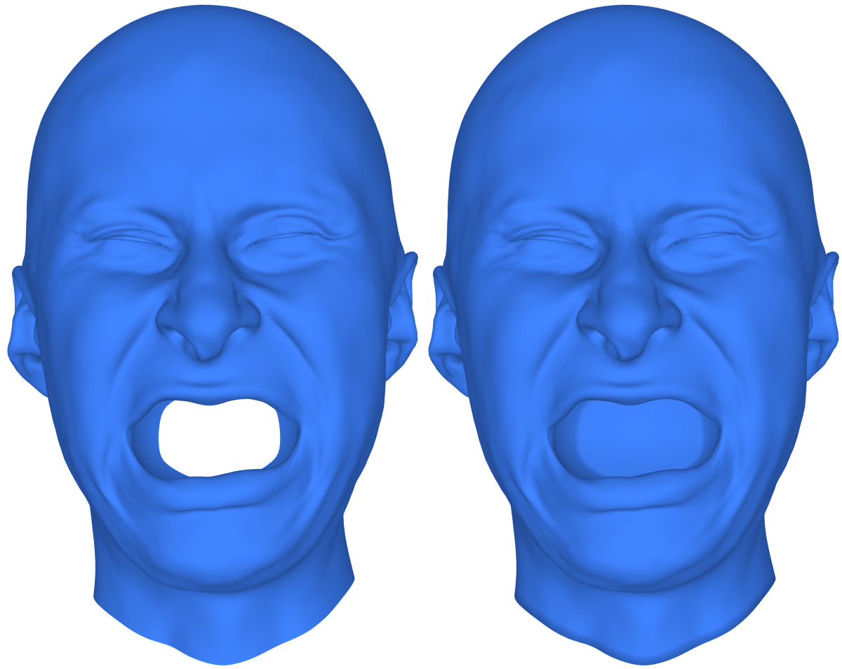
Interior of the mouth is broken
There may be times when the mouth is broken, as in the example below when compared to a good one.
Make sure that the Facial annotation and the result of the Track detector for the neutral frame are very similar. If they are not similar, adjust your annotation or redo the detection to achieve similar results.
If that doesn’t help, reduce the Detection Inner Lips Weight parameter.
It may also be caused by inaccurate Facial detection. Use the EditFacialDetection node to manually adjust the results of Facial detection from the LoadFacialDetection node. If it helps, you need to fix the detection in Track and export the Facial detection results again.
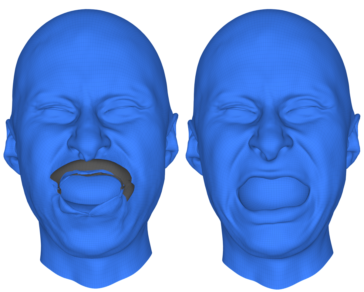
Mouth socket has a hole
The method requires that the basemesh has a mouth socket. The mouth socket allows detecting inner lip contours. The contours are defined as a border between one lip and another, or a lip and the mouth socket.
There may be times when your mouth socket has a hole. Below is an example comparing a mouth socket with and without a hole.
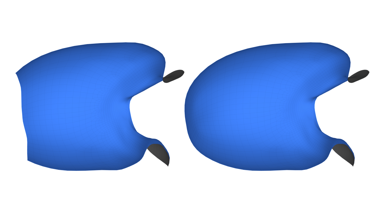
If the mouth socket has a hole in it, and this hole is visible from a front camera, the contour detection algorithm may fail. We suggest using solid mouth sockets. If the mouth socket has a hole, please make sure that the hole is not visible from the front camera connected to the ImageFacialWrapping node.
Or use the FillHoles node, however, keep in mind that this action will lead to a change in the topology, which means that you need to fix all topology-dependent things, these are all blendshapes, vertex masks, polygon selections, facial annotation and markers on geometry.
The fit is not very accurate
However, you can increase the accuracy of fitting by reducing the Sampling Radius or Smoothness Weight parameter. You can also increase the Num Component parameter especially if you are using many blendshape references.
Bad eye fitting
Make sure the your Facial annotation curves closely match the result of the Facial detection exported from Track for the neutral frame. If they don’t match, try to either adjust the Facial annotation or the detection in Track.
Make sure that your Facial annotation for the eyelids is very accurate. We highly recommend putting the eyelid contour exactly on the edge loop corresponding to the eyelash attachment line as opposed to the transition between the eyelid and the sclera. Also make sure that you track the eyelash attachment line (not the border of the sclera) inside Track.
Tip
If the skin is over the eye, as in the example above, then you need to move the Facial annotation closer to the edge of the eyelid. If underfitting occurs, that is, the skin does not reach the edges of the eyelids, then move Facial annotation further from the edge of the eyelid.
Can’t wrap a specific extreme expression
This probably means that your reference blendshapes don’t contain similar expressions. You can extend the set of reference blendshapes with a new expression to fix that.
You can do that by manually cleaning up the problematic expression using the Brush node and adding the resulting shape to the Blendshape References parameter. If you are using generic blendshapes, you can retarget the cleaned up shape to your generic neutral mesh before adding it to the Blendshape References.