Node-Graph Editor
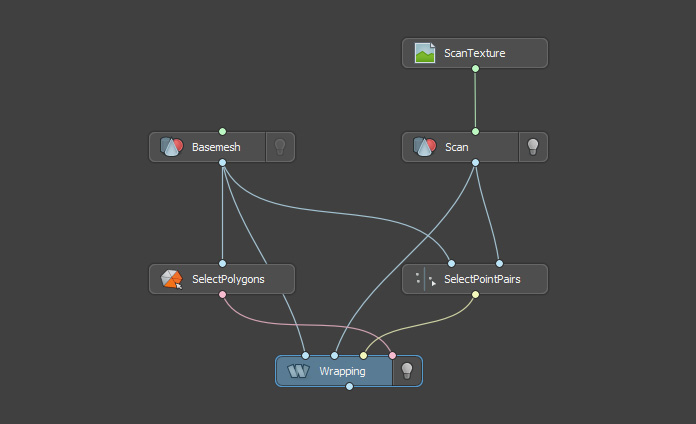
Everything you do inside Wrap is working with nodes: creating nodes, connecting nodes and changing node parameters.
Create a Node
To create a node press the Tab key or the Right mouth button inside the Node-Graph Editor to show the list of nodes and select a node type you want to create.
Node-list menu contains all the possible node types you can create. Node types are grouped in several sections: Geometry, Image, Selection, Alignment.
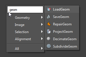
If you start typing a node name, you will see a look-up menu of nodes. Press Enter to select the best match.
Connect Nodes
In order to connect two nodes press LMB on the input/output of the first node and drag the cursor to the output/input of the second node.
Alternative way is to click and release LMB on the input/output of the first node, then click and release LMB on the output/input of the second node.
Each node can have several inputs and outputs.
Each input or output is associated with a specific type (Geometry, Image, PolygonSelection).
Every type has a unique color, for example Geometry is blue and Image is green.
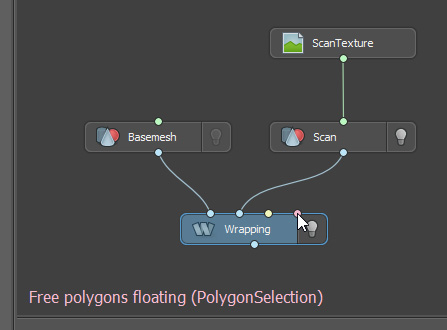
Tip
Hold the cursor over a node input to see its name and type.
Multiple Node Inputs
Some inputs may accept any number of other nodes’ outputs, for example, Render node Geometries input.
In order to connect nodes to such input you can select several nodes, and then press, drag and release LMB from output of one of them to the destination multiple input. After LMB release all of them would be connected.

Tip
The order depends on the connecting nodes positions: they would be connected from left to right, from up to down.
For faster connecting one node’s output to several inputs and can press SHIFT + LMB on destination node inputs instead of usuall clicking.
Connecting to a New Node
When dragging multiple outputs, press Tab or RMB to open the node menu. If a node is created, all held connections will be automatically connected to the created node.
Tip
When holding multiple connections, clicking on the node plug will result in data type matched connection.
Disconnect Nodes
Right-click on a connection curve and from the pop-up menu click Disconnect or click CTRL + LMB on it.
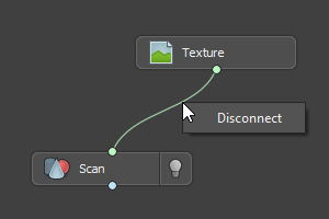
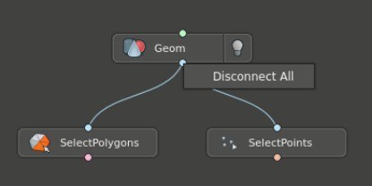
Right-click on an input or output of a node and from the pop-up menu click Disconnect All or click CTRL + LMB on it.
Check a Node Computation Status
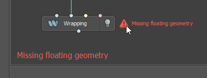
Each time an input of the node or a node parameter is changed the node is recomputed.
If the computation fails, you will see a warning sign on the left of the node. If you click on the warning sign or hold the cursor over it, you will see the an error message.
Check a Node Info
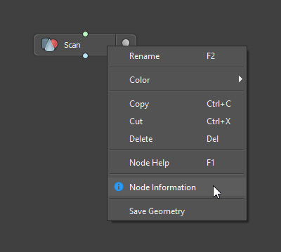
If you click the RMB on the node, in the context menu you will see the Node Information action.
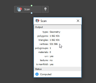
Clicking on the action will display a node information dialog which has some useful information about the node such as: a number of vertices or polygroups in the mesh, flags displaying whether the geomety is manifold or not, etc.
Rename Node
Each node has a unique name. Select a node and click F2 to rename it. Alternatively, click RMB on the node and select Rename from the context menu.
Change 3D-Node Visibility
Each node like LoadGeom that renders itself into a 3D-viewport has a lamp sign. Click the lamp sign to turn on/off the node visibility inside 3D-viewport.
Tip
CTRL + click on a lamp sign to toggle exclusive visibility inside 3D-viewport. The node will become visible while the rest of the nodes in the node-graph will be hidden from 3D-viewport.
Group Nodes
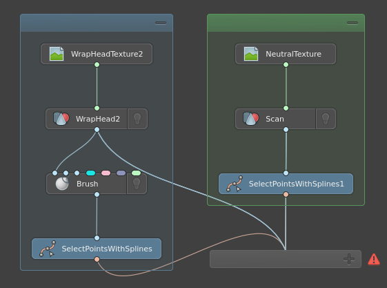
To group several nodes select them and hit CTRL + SHIFT + G. The frame will appear around them.
Tip
Groups share navigation principles with nodes. They can be selected, renamed, colored, copied and pasted, etc.
Group Specific Actions
Click and drag items |
to move them in groups |
Click and shake items |
to move them out of parent groups |
B while dragging items |
to unparent them from current groups |
Click and drag group header |
to move group around |
DEL |
to remove a selected group and all it’s contents |
CTRL + DEL |
to break a selected group and ungroup it’s contents |
Click on minus/plus sign |
to toggle group minimazed state |
Search a Node
To find and select an exact node press CTRL + F. Start typing a node name or type then hit Enter. The camera will center on the node. You can also find a group, if you named it.
Disable a Node
Disable nodes to prevent long computation of unused or reference nodes. Disabled nodes act as non-existing for Command Line Interface and Nodes >> Compute Frame Range background process.
CTRL + D |
to toggle disabled state for the selected nodes |
CTRL + D on group |
to toggle disabled state for the group’s contents |
CTRL + SHIFT + D |
to also toggle all dependent nodes, since they can’t be computed with disabled input |
Lazy Node Evaluation
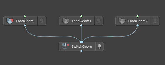
Wrap doesn’t compute nodes if it’s not neccessary to save your time in larger projects. Nodes are computed if:
Node is shown in Viewport3D (bulb is turned on).
Node writes something on a disk, e.g. SaveGeom, SaveImage, and other save nodes.
Node is selected in graph.
Node is enabled. Disabled nodes explicitly don’t compute.
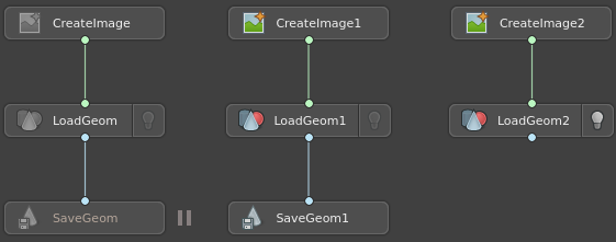
Compute All Nodes and Command Line Interface: cares only about enabled saving nodes. It will not compute anyting shown in Viewport3D.