 FixIntersections
Attempts to fix self-intersections in an as-rigid-as-possible manner. Allows the user to define which vertices will be transformed and how the final result will be mixed with the original model (for a smooth transition). Also allows to provide a collider geometry that will not be deformed, but instead used to deform input geometry in case of intersections between them.
Note
May require parameter tuning in order to achieve the desired result.
Ideally, geometry should not have holes in it. If it does, they are internally filled, similar to FillHoles (option Triangle Fan With Extra Point). That requires geometry to be manifold. To produce manifold geometry from non-manifold, RepairGeom can be used.
Attention
The node is not guaranteed to give good results if the collider geometry has self-intersections.
Thus, it is advised to check if FillHoles does not produce any self-intersections.
Use Cases
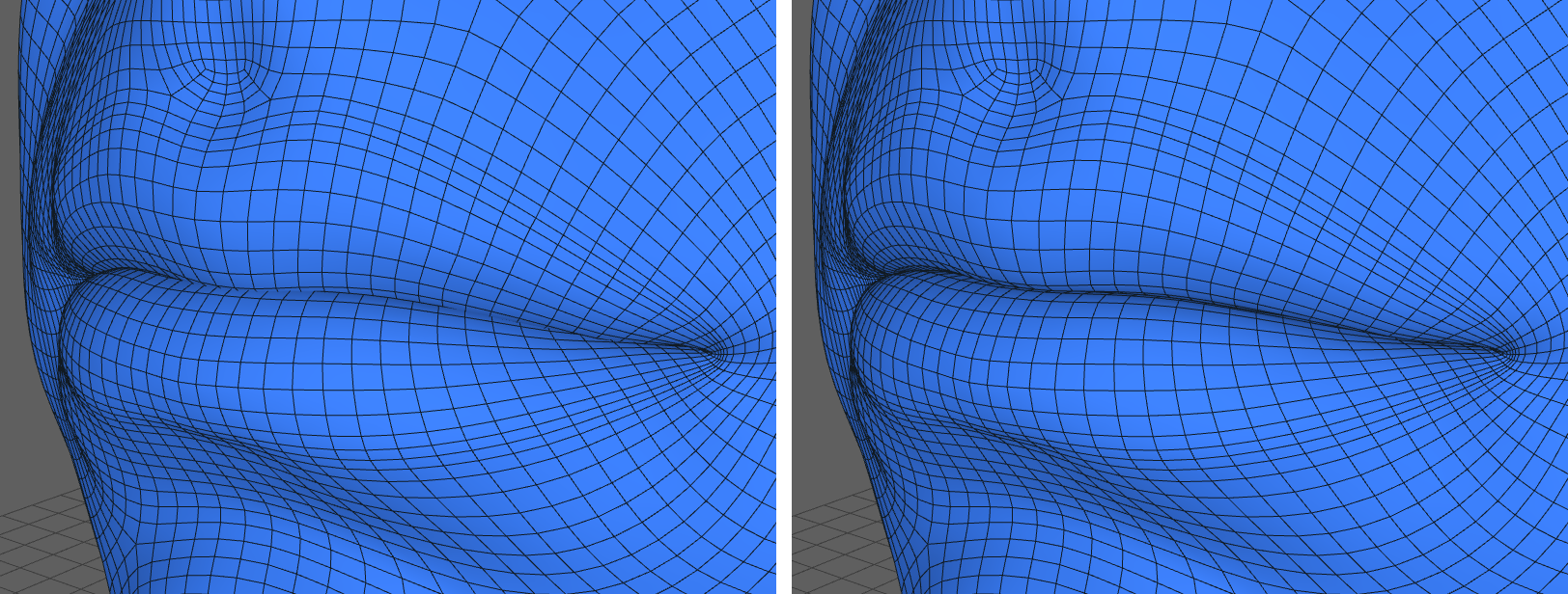
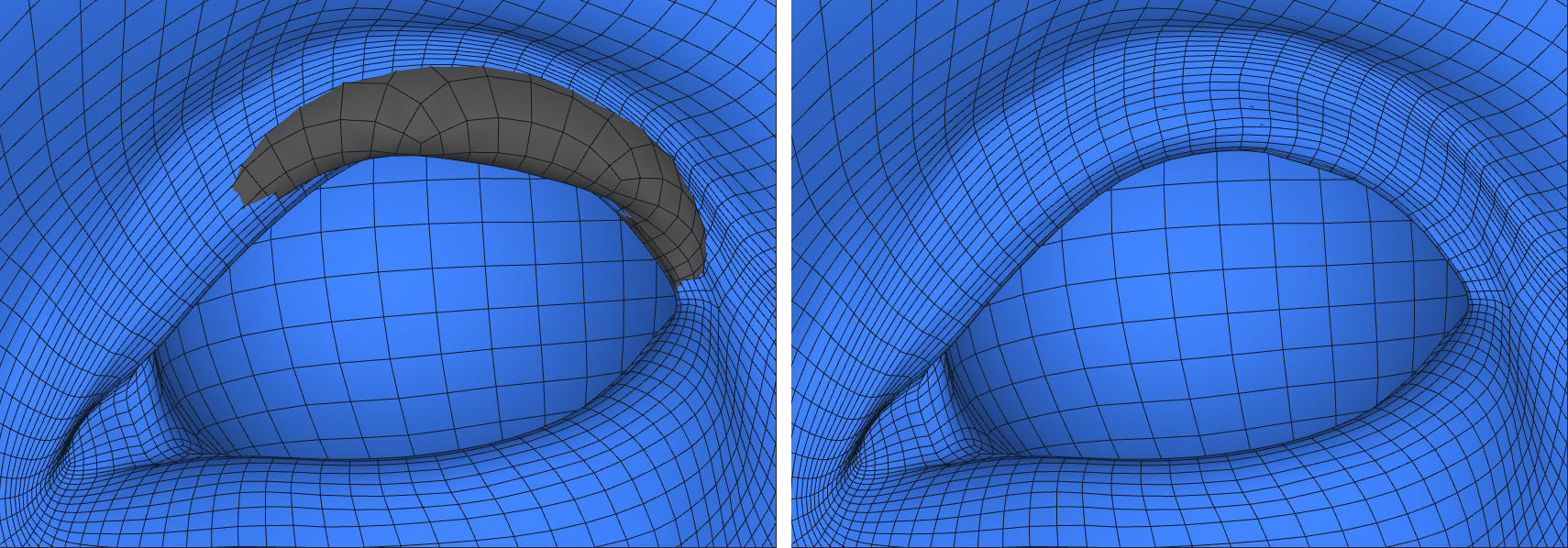
Wrapping often produces self-intersecting geometry, with most frequent regions being lips and eyes.
Eye sockets usually undergo rigid transformation during wrapping, which may result in intersections with eyelids.
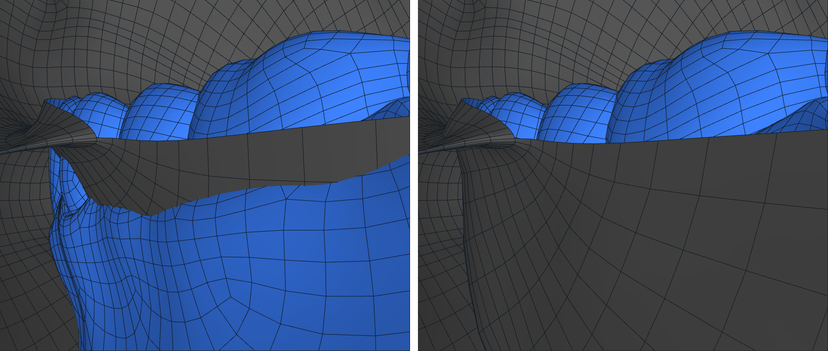
Teeth usually come as a separate object and produce intersections with lips and mouth socket upon merging.
Inputs
- Geometry
GeometryGeometry to fix intersections in.- Floating Vertex Mask
VertexMask(optional) A selection of vertices to be transformed, with their positions interpolated between the original model and the final result depending on the mask values, similar to MixGeom.All vertices, if not specified.
- Collider Geometry
Geometry(optional) Geometry that will not be deformed, but used to deform Geometry instead.None, if not specified.
Output
GeometryGeometry with its self- and external intersections fixed.
Parameters
- Max Iterations:
max number of times intersections will be detected and optimization will be launched.
- Iteration Accuracy:
max optimization error over all vertices. Values closer to 0 lead to theoretically higher precision, but might drastically increase computation time.
- Smoothness Weight:
how smooth the deformation should be.
- Initial Vertex Weights:
how much the vertices should stick to their initial positions.
- Collision Weight:
how much to prioritize collision resolution.
- Collision Weight Decay:
how much to consider collisions from previous iterations. Ranges from 0 (only consider collisions from current iteration) to 1 (equally consider collisions from all iterations).
- Resolution Distance (cm):
Desired distance between previously intersecting regions.
- Max Collision Distance (cm):
Intersection points separated by distance larger that this value will not be considered.
- Detect From Collider:
if collider geometry is provided, collision detection algorithm will use its vertices along with input geometry vertices to detect external intersections.
- Detect Self-Intersections:
if not checked, the algorithm will only detect external intersections with collider geometry and ignore self-intersections.
Note
Smoothness Weight, Initial Vertex Weights and Collision Weight are subject to balancing. For example, higher Smoothness Weight may lead to unfixed intersections. A general rule is to keep them between 0 and 10. However, setting both Smoothness Weight and Initial Vertex Weights to 0 is not advisable, as it makes the problem underdefined.
Note
Iteration Accuracy of 0.1 or 0.01 is usually sufficient, but harder problems might require more accuracy. If the problem is easy enough, changes of Iteration Accuracy may result in no visually noticeable difference.
Tip
Due to the optimization nature of the algorithm, the resulting distances might not be exactly equal to Resolution Distance (cm). Moreover, not all intersections might even be fixed in the end. If that is the case, try increasing Resolution Distance (cm). An alternative solution is to increase Max Iterations, but this comes at the cost of speed.
If the result is unsatisfactory (distances appear inconsistent), a viable option is to leave a small (possibly 0) value of Resolution Distance (cm) and apply a second FixIntersections with a desired Resolution Distance (cm) to the output.
Common Pitfalls
- No Vertices Intersection
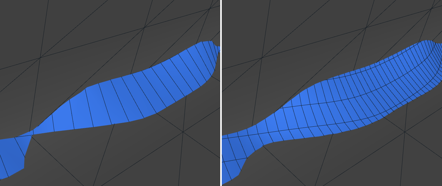
Collision detection algorithm uses vertices to determine if an intersection occured. Intersections between polygons that do not involve any vertices will not be detected, and, in fact, may lead to false positives. False positives may result in non-colliding parts of the model being dragged to each other, forming “spikes”.
Thus, it is advised to check if there are no such intersections, or use SubdivideGeom if any.
Spikes may also appear because of multiple overlapping intersections or multiple intersections of different kind. If that happens, try lowering Collision Weight Decay. It might be the effect of one of the previous collisions. If that does not help, try lowering Max Collision Distance (cm) to exclude these false intersections.